|
|
|
Who's Online
There currently are 5894 guests online. |
|
Categories
|
|
Information
|
|
Featured Product
|
|
|
 |
|
|
There are currently no product reviews.
 ;
Exactly what I needed to be able to bring the amp back to life... will come back to this site the next time I need schematics.
;
Information was accurate and very helpful.
However the continuity made it a little difficult to follow from one page to the next.
 ;
Very very good as usual very trustable site. Perfect!!!!!!
;
The Service Manual received was helpful. Good copy of original document.. I recomend all of my friends about this technical page.
;
Perfect, complete manual, exactly what I needed. Recommended to everyone.
SERVICE CONTROL ADJUSTMENT
B1 POWER SUPPLY ADJUSTMENT 1. Set VR641 to be mechanical centre before pressing the main switch. 2. Tune the receiver to PAL circular pattern. 3. Set brightness and contrast controls to normal. 4. Connect digital V-meter to test point "TP-B". 5. By using VR641, adjust voltage to 130 ± 0.5 V.
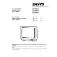
V-Outout +8V SW1901 SW1902 SW1903 SW1904 Prog.+ Prog.Vol.+ Vol.Q641 VR361 VR131 T141 T481 TP-E o-coupler
6. Set screen VR for one colour to be just visible. [BIAS VR ADJUSTMENT] 7. By using VR601, VR611 or VR621, adjust line to be white. 8. Set screen mode OFF, how to set refer to "service mode" [DRIVE VR ADJUSTMENT] 9. By using VR602 and VR612, adjust white balance. HIGH VOLTAGE & WIDTH ADJUSTMENT [HIGH VOLTAGE ADJUSTMENT] 1. Tune the receiver to circular pattern. 2. Set brightness and contrast controls to maximum. 3. Connect digital V-meter to both terminals of R224, and high voltage meter to CRT anode. 4. Confirm high voltage to be 25.0 ± 1 KV at beam current 1.1mA, and less than 28.0 KV at 0 beam current. [H-WIDTH ADJUSTMENT] 5. If H-width is too wide or narrow, connect or disconnect a lead wire J213. 6. Reconfirm high voltage.
Q432
VR641
Q681 +B ADJ.
SIF Board
SW601 F601
IC801 CPU A101 Tuner
RC Transformer TP-
AFT ADJUSTMENT 1. Tune the receiver to the clearest station. 2. By using T141, adjust AFT to obtain the best picture.
Fuse Main switch
T101
J213
Q461 T611
T141
IC651
IC652
IC1202
IC501 +12V
VR501 V-Size
IC271 1H Delay
Q432 H-Output
IC281
H-Centre
Q-SOUND Board
V-CENTRE ADJUSTMENT 1. Tune the receiver to circular pattern. 2. Adjust V-centre by using SW501.
AGC Int./Ext. SW. VR641 IC1201 AV2 SW.
SW501 V-Centre 611
VR361
VR131 IC1202
1. Tune the receiver to circular pattern. 2. Adjust V-size by using VR501. AGC ADJUSTMENT VR131 NOTE: Do not attempt this adjustment with weak signal. 1. Tune the receiver to the clearest station. 2. Set AGC VR(VR131) in direction which causes snow noise to appear, then in the opposite direction until snow noise just disappears. GREY SCALE ADJUSTMENT [SCREEN VR ADJUSTMENT] 1. Tune the receiver to the white pattern. 2. Set brightness and contrast controls to normal. 3. Set VR602and VR612 to be mechanical centre. 4. Turn VR601, VR611 and VR621 fully counterclockwise. 5. Set mode to one horizontal scanning line, how to set refer to "service mode"
T451
Scart 2
Scart 1
V-SIZE ADJUSTMENT
T101
Flyback TP-B
Q501
TP-E
A101 Tuner Transformer
FOCUS ADJUSTMENT By using FOCUS VR, adjust focus control for good scanning lines.
IC201 IF/Video/Croma/Def. Q501 H-Centre SIF Board
IC501
VR501 V-Size
IC271
H-Output
IC281
V-Centre
Q-SOUND Board
SW501
VR501
AV2 SW.
Scart 2
Scart 1
AGC Q4 Int./Ext. SW.
IC1201
VR361
-7F7JGV
Converter T
J213
IC201 IF/Video/Croma/Def.
H-CENTRE ADJUSTMENT 1. Tune the receiver to circular pattern. 2. Adjust H-centre by using VR361.
1H Delay
V-Outout
SW501
|
|
|
> |
|