|
|
|
Who's Online
There currently are 5974 guests online. |
|
Categories
|
|
Information
|
|
Featured Product
|
|
|
 |
|
|
There are currently no product reviews.
 ;
complete part-lists and pcb layout, schematic diagram is good enlargable,
;
Excellent, fast delivery, excellent product. Good luck!
;
This manual is for the usa model only. But it is clear
, accurate and comprehensive, including board layouts and schematics.
I found it extremely useful for my mitsubishi dp-86da, but the same diagram would also work for the realistic lab5000 and hi fi 80. Thanks.
;
Great to have extra resources for Service Manuals, Now days you can really not trouble shoot efficiently without one , Wayne at IRIONS TV & ELECTRONICS REPAIR Clearwater , Fl. 33755 727-446-7955
 ;
For five bucks you can barely buy a hamburger. Or for the same five bucks you can buy a service manual. Much more useful. (and better for your health, depending on where you buy your hamburgers).
Yes, there are free manual sites out there, but if they don't have what you want, you have to pay.
And five bucks isn't much. Not for full specs, schematics and adjustment and parts replacement procedures.
My only criticism is that grayscale illustrations aren't well rendered, but I've seen worse.
Schematics and text are clear.
I'll be happy to purchase from here again.
Mike
[email protected]
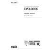
SERVICE CONTROL ADJUSTMENT
B1 POWER SUPPLY ADJUSTMENT 1. Set VR641 to be mechanical centre before pressing the main switch. 2. Tune the receiver to PAL circular pattern. 3. Set brightness and contrast controls to normal. 4. Connect digital V-meter to test point "TP-B". 5. By using VR641, adjust voltage to 150 ± 0.5 V.
V-Outout SW501 +8V TP-E o-coupler SW1901 SW1902 SW1903 SW1904 Prog.+ Prog.Vol.+ Vol.VR361 Q641 IC651
H-Output
VR641
Q681 T101 +B ADJ.
5. Set mode to one horizontal scanning line, how to set refer to "service mode" 6. Set screen VR for one colour to be just visible. [BIAS VR ADJUSTMENT] 7. By using VR601, VR611 or VR621, adjust line to be white. 8. Set screen mode OFF, how to set refer to "service mode" [DRIVE VR ADJUSTMENT] 9. By using VR602 and VR612, adjust white balance. HIGH VOLTAGE & WIDTH ADJUSTMENT [HIGH VOLTAGE ADJUSTMENT] 1. Tune the receiver to circular pattern. 2. Set brightness and contrast controls to maximum. 3. Connect digital V-meter to both terminals of R224, and high voltage meter to CRT anode. 4. Confirm high voltage to be 26.0 ± 1 KV at beam current 1.3, and less than 29.0 KV at 0 beam current. [H-WIDTH ADJUSTMENT] 5. Adjust VR462 to obtain proper VR642
T611 Converter Trans Transformer
SIF Board
IC801 CPU A101 Tuner
F601 SW601
AFT ADJUSTMENT 1. Tune the receiver to the clearest station. 2. By using T141, adjust AFT to obtain the best picture.
611 V-Centre
T481
Main switch Fuse
T141
TPRC Transformer
H- width. 6. Reconfirm high voltage. H-CENTRE ADJUSTMENT 1. Tune the receiver to circular pattern. 2. Adjust H-centre by using VR361.
VR501 SW501 1H Delay Q-SOUND Board
Q432
IC652
Q501
H-Centre
VR131
Q-SOUND Board
V-CENTRE ADJUSTMENT R224 1. Tune the receiver to circular pattern. 2. Adjust V-centre by using SW501.
AV2 SW.
IC501 +12V
VR501 V-Size
IC271 1H Delay
Q432
IC281
IC1201
H-Width
Scart 2
Scart 1
IC1202 T141 AGC Int./Ext. SW. VR641
V-SIZE ADJUSTMENT 1. Tune the receiver to circular pattern. 2. Adjust V-size by using VR501.
IC1202 Q461
SIF Board
VR131
AGC ADJUSTMENT NOTE: Do not attempt this adjustment with weak signal. 1. Tune the receiver to the clearest station. 2. Set AGC VR(VR131) in direction which causes snow noise to appear, then in the opposite direction until snow noise just disappears.
FOCUS ADJUSTMENT By using FOCUS VR, adjust focus control for good scanning lines.
IC201 IF/Video/Croma/Def. Q501 VR361 VR462 H-Centre
IC501 V-Outout
V-Size
IC271
H-Output
V-Centre
GREY SCALE ADJUSTMENT [SCREEN VR ADJUSTMENT] 1. Tune the receiver to the white pattern. 2. Set brightness and contrast controls to normal. 3. Set VR602and VR612 to be mechanical centre. 4. Turn VR601, VR611 and VR621 fully counterclockwise.
TP-E
IC281
VR131
Scart 2
Scart 1
SW501 -7-
VR501
AGC Int./Ext. SW.
IC1201 AV2 SW.
VR361
A101 Tuner Flyback TP-B
T451
F7VVV
J213
IC201 IF/Video/Croma/Def.
Q462 T101
|
|
|
> |
|