|
|
|
Who's Online
There currently are 6043 guests online. |
|
Categories
|
|
Information
|
|
Featured Product
|
|
|
 |
|
|
There are currently no product reviews.
 ;
Veramente completo, dettagliato e perfetto nella visione. Perfect, thanks!
 ;
Fully functional usable service manual. Considering the age of the manual and device quality was better than expected
;
Thank you very much, I've been very happy to find this manual on "Owner Manual". It's a perfect copy and it has been really useful for my work!
;
It took about 24-hours after my payment before I was able to get to the download. Apparently, payment processing is not 100% automated. That is no big deal, just be aware of that going in.
After I got to it, it was in good shape, easy to read, etc. Not some cheap FAX copy looking thing.
Also, this site was the cheapest I found. Another Plus!
;
Good price, very legible manual, exactly what I needed -- but had to wait a day to actually get the download of the manual. Would have preferred to download it immediately after payment rather than waiting for someone to "process" my order. I was surprised that I had to wait that long.
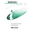
Main Board /Pannello Principal
Circuit side/Lato del Circuito
K12A J10EA020N 2 FRONT-IN 1
R1251 1/10 GJ2.7K R1252 1/10 GJ6.8K C1251 16EM 10
K12B J10EA 050N
1 SC2-IN
MONITOR-OUT
Q1251 2SC2812L6 :BC848B
R1253 1/10 GJ82K R1254 1/10 GJ82K
1
16
R1264 1/10 GJ82K Q1252 2SC2812L6 :BC848B C3431 EM1 R1265 1/10 GJ470 R1266 1/10GJ 2.2K C3433 EM1
5
2
15
3
R1257 1/10 GJ470 R1256 1/10 GJ82K R1258 1/10 GJ2.2K
14
R1263 1/10 GJ82K
IC3431 TDA8424
4
13
R1262 1/10 GJ82K
1
C3432 16EM100
IN-L
20
5
12
2
V-CAP
19
IC1251
HD14052BP :MN4052B :TC4052BP :UPD4052BC
6 7
11 10
3
IN-R
18
8
9
C3434 25KZ0.1FA :KZ0.1FA
4
VCC
17
5
C3435
AGND
BASS-L
16
F601 Main switch
KK 0.033BA :25KK 0.033BA Q3484 2SC2812L6 :BC848B
6 7
C3436 KK5600BA
BASS-R
BASS-L
15 14
C3438 25KK 0.033BA :KK 0.033BA C3437 KK 5600BA
VR462 SW601 H-Width
BASS-R
TREBLE-L
Q461
Fuse
R3482 1/10GJ 2.2K
GND
J3401 1/10GZ 0.0 C3486 PM 0.47D J3481 1/10GZ 0.0 C3409 PM 0.47D
IC3401 TDA9840/V2 R3401 1/10 GJ100 C3401 16EM10 R3402 1/10 GJ100 X3401 V10B1750N
8
TREBLE-R
OUT-L
13
R3432 1/10 GJ100
Q462
1
SDA
SCL
20
9
OUT-R
SCL
12
Q613
Q3482 2SC2812L6 :BC848B R3481 1/10GJ 2.2K
GND
2
C3405 16EM 100 C3402 KK0.01BA
C-AGC
XTAL
19
10
DGND
SDA
11
R3431 1/10 GJ100
T451 Q612
3
C-LP
VCC
18
C3421 KZ 0.01FA C3412 KK0.01BA C3422 16EM 10 Q3431 2SC2812L6 :BC848B
TP-BFlyback Transformer Q611
4
C3403 25KZ0.1FA :KZ0.1FA C3404 25CG 3300CA
C-DCL
C-D2
17 16
T611
Converter Transformer
5
Vi pil
GND
6
Cref
C-D1
15
D615 J213 T481
Photo-coupler RC Transformer
C3408 EM2.2 T3401 L21B0120N
C3411 KK0.01BA R3434 1/10 GJ1.5K
R3433 1/10 GJ100 Q3432 2SC2812L6 :BC848B
7
AF1
L-OUT
14
8
AF2
R-OUT SCART OUT-L SCART OUT-R
13 12
R3436 1/10 GJ1.5K R3435 1/10 GJ100
H-Output Q501
C3406 1/10GZ 0.0
C3407 CJ47CA
R3403 1/10 GJ30K
Q432
9
Vi3
10
C3409 EM2.2
Vi4
11
VR641 Q681
ASSY,PWB,AUDIO F2RT 1AA0B10E230BB
R3477 1/10GJ2.2K
IC651
R3479 1/10GJ2.2K
SW501 V-Centre
K34A J10EQ100N
PB002 1AA4B10E0600B
K34B J10EQ100N
1H Delay +8V
R-OUT
L-OUT
REGOLAZIONI DI SERVIZIO TECNICO
H-Centre
REGOLAZIONE DELL�ALIMENTATORE B1
1. Regolare VR641 in modo che sia centro meccanico, prima 7. Per regolar il livelli, premere il tasto livello.
TV/AV
GND
SDA
SCL
S2
1
10
1
10
AV2
ALLINEAMENTO DI CIRCUITO
10k� 0.002µF 75� 1k�
VR131 VC141
di premere l�interruttore principale. 2. Sintonizzare il ricevitore sull�oscillogramma circolare PAL. 3. Regolare i comandi di luminosità e contrasto sui livelli normali. 4. Collegare il misuratore V digitale su �TP-B�. 5. Servendosi di VR641, regolare il voltaggio su 130 ± 0,5 V (per 21 pollici). Servendosi di VR641, regolare il voltaggio su 150 ± 0,5 V (per 25 pollici).
+
a b
T101 T102 IC1201
Audio-output
IC001 Int./Ext. SW.
IC1202 T141 AGC
Allineamento VIF
[REGOLAZIONE VR DEL BIAS (POLARIZZAZIONE)]
7. Servendosi di VR602, VR612 o VR622, regolare la linea in modo che sia bianca. 9. Per tornare al modo di funzionament TV, premere il tasto Richiamo. 8. Regolare VR di schermo per un solo colore in modo che sia ben visibile.
Sonda di ingresso Regolazione Servendosi di T141, regolare "P" in modo che sia di ampiezza massima.
Sonda di uscita
AV2 SW. SIF Board
IMPOSTAZIONE DC 15.5V Tensione AGC (4.3-4.5V) Sonda di uscita Sonda di ingresso Marker frequency Sweep ATT 0dB=176mVrms/75 C644 + IC201-pin48 IC201-pin45 (Side b) IC201-pin7 38.9MHz 20dB
Forma d�onda VIF
P
IC810 Band SW. Audio Board
REGOLAZIONE AFT
1. Sintonizzare il ricevitore sulla stazione più chiara. 2. Servendosi di T141, regolare AFT per ottenere l�immagine migliore.
A101 Tuner
REGOLAZIONE AGC
NOTA: Non tentare questa regolazione con un segnale debole. 1. Sintonizzare il ricevitore sulla stazione più chiara. 2. Regolare AGC VR(VR130) nella direzione in cui appaiono i disturbi da neve, quindi regolare in direzione opposta nel punto esatto in cui i disturbi da neve scompaiono.
[REGOLAZIONE VR DEL DRIVE (ECCITAZIONE)]
9. Servendosi di VR601 e VR611, regolare il bilanciamento del bianco.
REGOLAZIONE DI ALTO VOLTAGGIO E DI AMPIEZZA [REGOLAZIONE DI ALTO VOLTAGGIO]
1. Sintonizzare il ricevitore sull�oscillogramma circolare PAL. 2. Regolare i comandi di luminosità e contrasto sui livelli massimi. 3. Collegare il misuratore V digitale su entrambi i terminali di R224 (lato sinistro) (+), e il misuratore di alto voltaggio sull�anodo CRT. 4. Confermare che l�alto voltaggio sia 25,0 ± 1 KV alla corrente di fascio di elettroni 1,0, e meno di 28,0 KV alla corrente di fascio di elettroni 0 (per 21 pollici). Confermare che l�alto voltaggio sia 26,0 ± 1 KV alla corrente di fascio di elettroni 1,1, e meno di 29,0 KV alla corrente di fascio di elettroni 0 (per 25/28 pollici).
Allineamento SIF
IMPOSTAZIONE DC 12V Tensione AGC Sonda di uscita Sonda di ingresso ATT di deflessione Frequenza segnalatore IC3801-pin11 IC3801-pin3 IC3801-pin1 (Side b) IC3801-pin12 10dB 38.9MHz Regolazione 1. Regolare la tensione AGC in modo che sia "A" = 0.5Vp-p. 2.Servendosi di T3801, regolare "P" in mod che sia uguale alla linea di centro. Forma d�onda SIF
REGOLAZIONE DELLA SCALA DEI GRIGI [REGOLAZIONE VR DI SCHERMO]
1. Sintonizzare il ricevitore sull�oscillogramma bianco. 2. Regolare il comando della luminosità su centro display e quello del contrasto su normale. 3. Regolare VR2601 e VR2611 in modo che sia centro meccanico. 4. Ruotare fino in fondo, in senso antiorario VR602, VR612 o VR622. 5. Quando si tiene premuto il pusante tasto �Funzione� (sul telecommando) e contemporaneameante si preme il pusante P v (sul televisore) apparivanno le seguenti indicazioni sullo schermo.
P
"A"
SIF In
-
+
P
ADJUST K1 K2 ST ID
DATA +000 +000 +000 +004 -050 -075 VOL 1.0
[REGOLAZIONE DI AMPIEZZA-H]
5. Se l�ampiezza H è troppo larga o troppo stretta, collegare o scollegare un filo in piombo J213 (per 21 pollici). Regolare VR462 per ottenere l�ampiezza H appropriata (per 25/28 pollici). 6. Riconfermare l�alto voltaggio.
Allineamento Pilot
IMPOSTAZIONE Regolazione Forma d�onda
Main Board /Pannello Principal CRT Board /Pannello Cinescopio
Circuit side/Lato del Circuito
SW1901 SW1902 Prog.+ Prog.SW1903 SW1904 Vol.Vol.+
Component Location/Lato del Componente
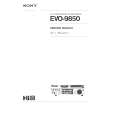
GENERAL BLOCK DIAGRAM FOR EB4 CHASSIS
F
Audio I/O
ATT MAX MIN SCREEN CPU Ver
REGOLAZIONE DI CENTRO-H
Oscilloscopio Ingresso di desidera
IC3401-pin5 Sistema B/G 27kHz Stereo
1. Sintonizzare il ricevitore sull�oscillogramma circolare. 2. Regolare il centro-H servendosi di VR361.
6. Premere il tasto �Funzione� (sul televisore) per selezione la funzione �SCREEN�.
RC Pre.amp
SW di sistema Deviazione Modo
Servendosi di T3401, regolare "P" in modo che sia di ampiezza massima.
A
REGOLAZIONE DI CENTRO-V
1. Sintonizzare il ricevitore sull�oscillogramma circolare. 2. Regolare il centro-V servendosi di SW501.
IC801 CPU
47 10 2 3 4 5 17 18 24 51 Control Keys
21P Scart: AV1
Audio I/O Video I/O
21P Scart: AV2
F
Video I/O Audio I/O
ADJUST K1 K2 ST ID ATT MAX MIN SCREEN SCREEN CPU Ver
DATA +000 +000 +000 +004 -050 -075 VOL 1.0
REGOLAZIONE DELLA DIMENSIONE-V
1. Sintonizzare il ricevitore sull�oscillogramma circolare. 2. Regolare la dimensione-V servendosi di VR501.
+B ADJ.
IC801 CPU
IC802
6 5
SCL SDA
49 50
2: Bright 3: Contranst 4: Colour 5: Sharpness V-In Functuin In(AV1/AV2) V-In CVBS In 6 1 8 Out 3
REGOLAZIONE DELLA MESSA A FUOCO
Servendosi di FOCUS VR, regolare il controllo della messa a fuoco per una buona scansione delle linee.
Q641
IC802 Memory IC810 Band sw.
VL VH U 52 1
14 X131 SAW Filter
16
24 23 22
G R BLK External CVBS in Internal CVBS in Q151 7 CVBS In Q152/Q154
SC1-OUT-L SC1-IN-L
TP-D
TU IF
45/46
21 15
SC1-OUT-R
B
RGB/BLK In
Q171
IC1202 CVBS int/ext sw.
SC1-IN-R 5V 12V
Tuner
IC652
IC271 1H Delay 11/12 14/16
R-Y/B-Y 28/29 R-Y/B-Y 30/31
13
CRT Unit
GND
GND
SIF Unit
MONO
Audio Unit
Q2601 Q2611
20
R G Q2621 HV
IC201 IF/Video/Croma/Def.
VR361
19 18 B Q431 37 41 48 H-Drive Q432 H-Outpit
IC501 +12V V-Outout
VR501 V-Size
IC271
IC281 Memory
Power Supply Circuit
Audio Out L, R
IC201 IF/Video/Chroma/Def. FBT IC501 Vert. Output
V-Drive 4 2 H V
T611 Converter Transformer
TP-E
B6: 12V B8: 5V B7: 8V
AC In Q612 Q613 IC651 IC652 B1: 150V B2: 25V B3: 15V B4: 24V V-Feedback
Audio In L, R
IC001 Audio Output
1/ 5 10/ 8 L, R Speakers
C512 VR501
DY
AF1 AF2 GND
Scart 2 R224
Scart 1
|
|
|
> |
|